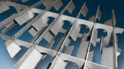
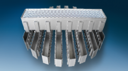
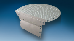
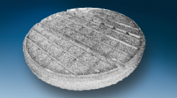
The following figure on the right side provides information about commercially available Droplet Separation systems and precisely defined, in which process conditions with respect to the limit drop size and stream velocity existing one separator is used.
| Seperation System | Limit Droplet [µm] | Free Vol. % |
|---|---|---|
| Separation by Inertia (vessel/ column) | > 100 | – |
| Cyclone or Cyclone liquid Collector | 50 – 100 | 10 – 20 |
| Impact baffle or Vane Type Separator | > 15 | 3 – 10 |
| Knitted Wire Mesh Separator | > 3 | 3 |
| Knitted Wire Mesh + Agglomerator | > 1 | < 3 |
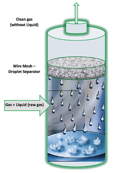
The application limits arise from the separation mechanism, which come into effect depending on the droplet size and the gas velocity.
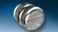
The column figure is showing a droplet separation process with an installed knitted wire mesh droplet separator in the top of the column.
The separation of liquid droplets is based on the effect, that the particles cannot follow the streamlines of the gas when they hit an obstacle and stick to a periphery.
Each individual wire of the knitted wire mesh separator constitutes an obstacle in a gas stream, so that a deflection of the streamlines occurs. Entrained droplets cannot follow due to its inertia this redirection and rebound on the single wire. The mist important separation mechanism are:
- Separation by Inertia
- Separation by Interception
- Separation by Diffusion.
